
The hardware itself was designed to fit into the space for the original controller board and transformer. Because the box is a metal box, it was necessary to mount the wifi antenna outside the box to provide good reception. A 7' SMA cable allows the wifi antenna to run outside the breaker box. The wifi module selected had a detachable antenna with a SMA connector so a cable could be added.
Power comes from the same 120V AC circuit as the original controller and powers both a DC power supply (for the BBG) and a transformer (for the Pump relays). The DC power supply is a potted 1A power supply. The transformer is a generic 120V in/20V 1A transformer. Since each relay consumes around 80ma when activated, 1A is more than adequate to power the relays. A schematic of each relay channel is shown here. The relay board was designed to use the same connectors as the original controller board. While the BBG GPIO could have driven the relay using transistors, the IXYS optical relay adds another layer of isolation to the BBG and costs almost the same as a couple of transistors. The CPC needs a little less than 1ma to trigger, which the GPIO output pins are capable of supplying. I also used a small R/C circuit off the diode bridge to reduce ripple. I had bunches of 47uF caps, so for my case it was cheaper(free) to use 6 caps instead of one larger one. For temperature measurements, I used the circuit here. For 10K probes I used a 10K supply resistor and for the 50K probes, I used a 50K. That sets the voltage to the midpoint of the A/D at 75 degrees. I also added a 22uF cap across the probe to minimize noise. The A/D seems to need it to keep noise down. The connections for the thermistors on the original board used screw terminals, so the new board uses screw terminals as well.
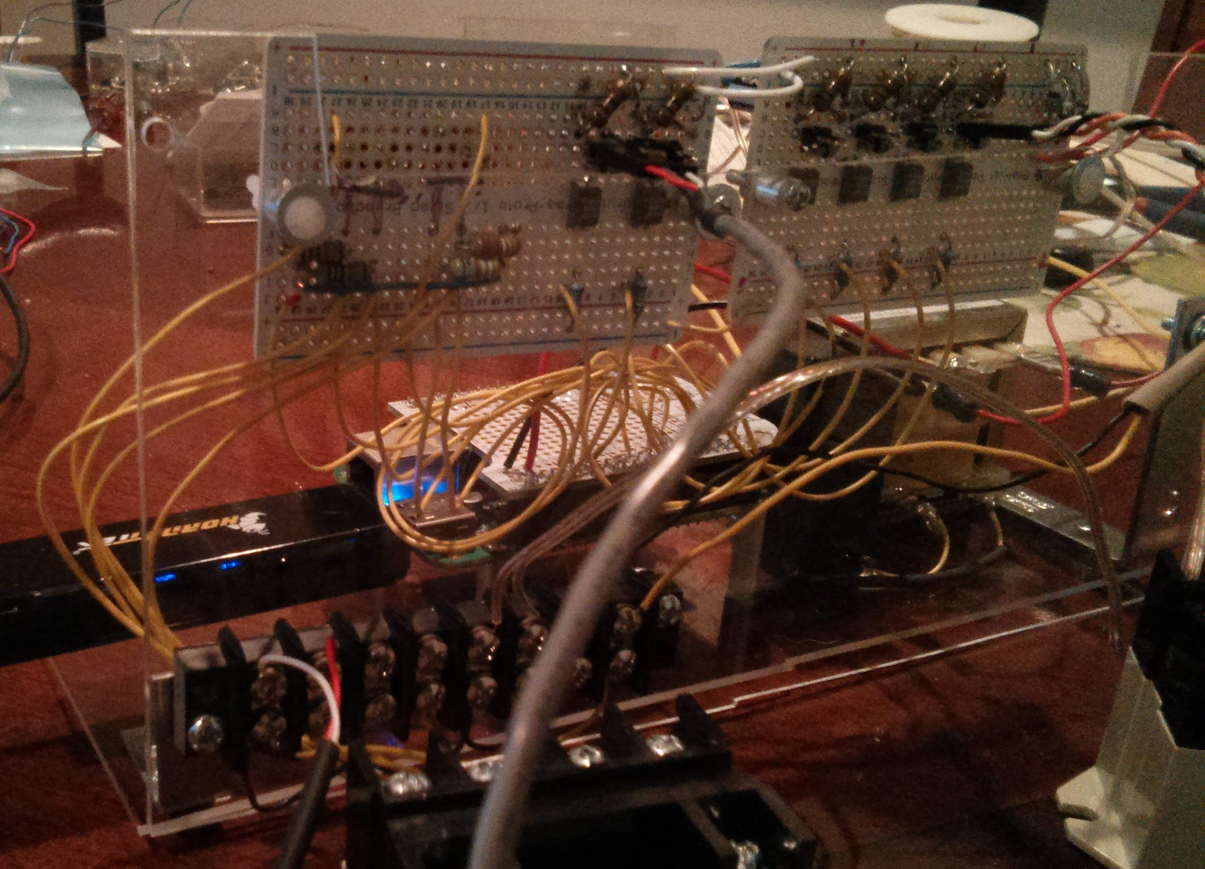
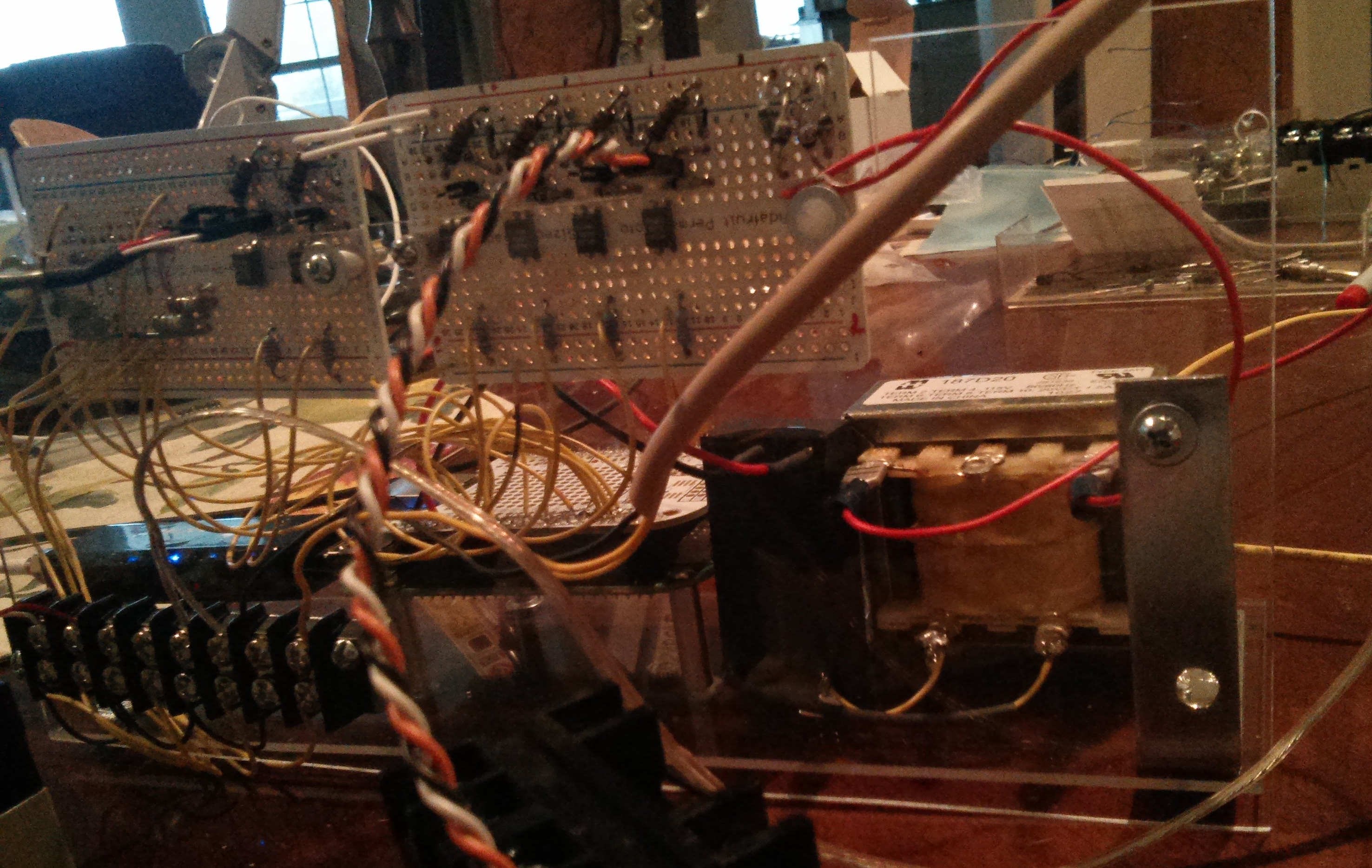
The boards and transformers are mounted on plexiglass. I've used plexi before. It is easy to cut and drill, and in this case, being transparent helps make the status LED's visible. The boards used include a cape proto board as well as 2 half sized proto boards, all from adafruit. From photo1 and photo2, you can see the positions of the component and board placement. The temperature circuitry is mounted on the left side of the left board and 2 relay drive channels are mounted on the right of the left board. The remaining 4 relay channels and the diode bridge to generate the relay drive voltage are on the right proto board. There is no circuitry on the proto cape, just wires soldered to connect to the proto boards.